Reel Ferro Open Breakdown
By: Joe Scacciaferro

Original Design spec:
Since this assignment was an in-house project for Ferro it was only logical that they would rely on the talents of their senior designer. Swen’s roll was expanded from designer to project manager of conceptual development and design, “We were looking to make an animated open for a new Ferro video series called REEL FERRO. Since the Ferro logo is actually a filmstrip I decided to expand on that image and expand that concept by incorporating a film projector into the animation” Swen explains.
Can be seen:
As the intro on all of the videos for both Ferro Productions video series; Industry Experts and the Behind the Scenes series.
Concept to Element Development:
After the concept was agreed upon Swen began researching different projector images on the web, “I looked at huge theater projectors and new digital projectors, then began narrowing my focus down to an old school 16 mm reel to reel projector; The style you’d find in any high school’s A/V room from the 50’s – 70’s.”
The selected image was imported into Cinema 4D. Since this was a flat 2D image and the animation spec called for a full 3D image, Swen’s first step was to redesign this projector image as a 3D model, “Using my pen tool I traced the outline and major components of the projector”. (see BEHIND THE WIZARDS CURTAIN Note: 1) “By tracing the object, it creates splines to the image.” Now using the Extrusion tools he was able to manipulate these images to create a 3D model of the projector”. (see BEHIND THE WIZARDS CURTAIN Note: 2)
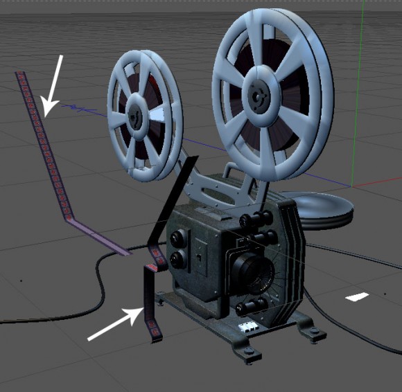
A few of the components were created separately. The film strip was created using a long simple rectangle and bending it to fit in the film path. The actual film look was created later which we explain in the next phase. The film reels were purchased from a preset pack and scaled to fit the projector model.
Texturing
To give the model’s skin a traditional metal look Swen used a few prepackaged textures. Blending these gave the image a true “old projector look”. The BUTTONS and LENS were also textured from those packs except this time he used a flat black plastic look. The NUMBERS on the buttons were created by using a flat image that when dropped on top of the knob gives the impression of the NUMBERS being screened onto the knob, ‘I did these rather than spend a lot of unnecessary design time creating each number in 3D”. (see BEHIND THE WIZARDS CURTAIN Note: 3)
The FILMSTRIP is another slight of hand / smoke and mirrors trick. Although it looks like the filmstrip is traveling through and around the reels it is actually just a mapped texture laid over a long rectangle, “I build one frame of the filmstrip in Photoshop and then tiled it in Cinema. To give the feel of movement I then animated the texture.” This technique gives the same visual impression of film moving without the processing time necessary to move the actual rectangle.
LIGHTING
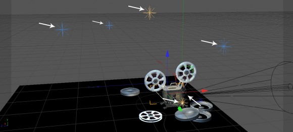
Since only one side of the image was dominant in the final design, lighting was fairly straightforward; Light the dominant side and shadow the backside. Secondly, to give the illusion of the projector running Swen added a Volumetric light emanating from the lens itself. (see BEHIND THE WIZARDS CURTAIN Note: 4)
ANIMATION
To begin the animation sequence it was determined that a “grand gesture” was needed. After some consideration Swen decided on the activation of an “ON” switch. The projector’s original switch was just a simple “toggle” switch. “The switch that was on the original image was to small… not a strong focal point.” Swen chose a common light switch and although this particular type would never be found on a real world projector, it integrated perfectly for story telling. After adding textures and modeling the common house light switch was transformed to the “grand gesture” necessary to kick start the animation.
CAMERA MOVES
“Typically I use one camera with a long tracking move. Due to the complexity of the animation story and knowing a single long shot would be boring, I opted to cut the piece into four moves, or “clips”. The first move starts with a push into the projector’s switch clicking on. The second angle is from the back of the projector. The third is a close up of the filmstrip moving into the projector. The fourth and last move pans from the projector to the actual projection on the screen. This sets up the beginning of each REEL FERRO video. (see BEHIND THE WIZARDS CURTAIN Note: 5)
Camera Move Breakdown (green lines are the different angles)
FINAL COMPOSITE
These clips where then imported into After Effects and cut together to create the total animation and add the final color and flickering film FX.
The last phase of the process is the audio sweeting. In this case the project was sent out of house for the music and sound FX mix. Swen reveals, “When I say out of house I really mean of my office and into the audio studio down the hall.”
Finished Product
Designers final notes:
Although, I felt like cheated a little in that I used several clips rather then on long continuous move, it always comes to a balance of your time budget vs your personal integrity challenge. In the end this animation came out way cooler then my original vision.
BEHIND THE WIZARD’S CURTAIN:
NOTE 1: You should always trace and create the major components separately. This way when you begin modeling / animating you will have the freedom to tweak and adjust each piece. It also saves a lot of time in rendering.
NOTE 2: These tool allow you to expand a 2D image into 3D. You can control the XYZ axes of image as well as bevel edges and dozens of other tweaks necessary to return a 2D image back to its original 3D real life appearance.
NOTE 3: This particular technique of texture mapping is similar to how real world manufactures create a flat label for a bottle then wrap it around the bottle. As opposed to the costly method of printing directly to a circle surface like a bottle.
NOTE 4: Volumetric light is a light that the “beam” remains visible. In the real world this light is usually created by adding smoke or dust into the lights beam. Thereby revealing the beam as well as its effect.
NOTE 5: using Cinema cameras can be best understood if you visualize the process as you would real cameras shooting a real projector. i.e. place a camera in the first position and do a slow push as the switch turns on. Reposition the camera to the back of the projector and record. Again reposition the camera to capture a close up of the film moving and finally do a camera move from the projector to the screen.


